
After going back and forth on different options for improving the STacy's screen, I have decided to replace the screen altogether with a LED-backlit LCD screen.
The biggest reason was that the EL-backlight was poor. I had just bought a new sheet and it was already dim. Also, to use the STacy screen, you're stuck with the stupid DC-DC converter to generate -24v for the LCD and 85VAC @590Hz to the EL-backlight.
First I had to find a suitable replacement screen. I found a good candidate on eBay. It's a 10.1" 1280x800 LCD panel and fits more or less inside the STacy bezel. It has pretty much the same aspect ratio, and is a multiple of both W & H resolutions (640 x 2 = 1280 and 400 x 2 = 800). STacy is actually about 16:10 (640/400 = 1.6 and 223mm/147mm = 1.52) so theoretically should be almost perfect. I bought it in March, and received it today.
The controller I bought at the same time was also from eBay. It came pretty fast.
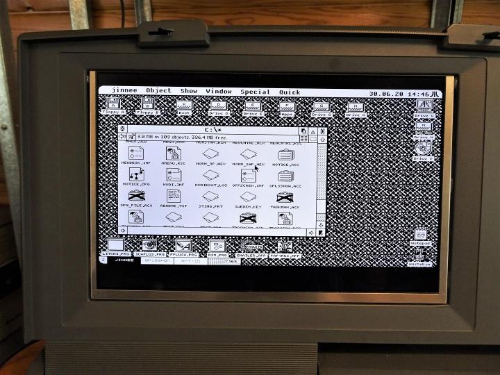
I tested the screen on the STacy and was chuffed that it worked but disappointed that the controller does not utilize the whole screen. It detects a 800x480@72Hz signal for some reason. The controller has basic adjustments but nothing like my NEC Multisync LCDs. I still decided to go for the upgrade.
I will have to do something to the LCD bezels. The display is stretched to 16:9 ratio.
Close-up of the gap.
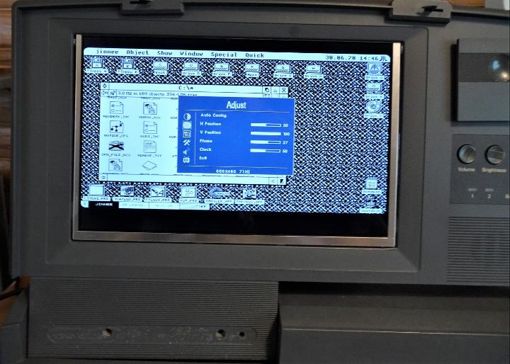
The controller has a remote and an ok OSD. It actually remembers all settings even if powered off and disconnected so that's really nice.
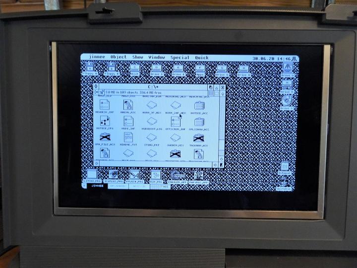
This is in 4:3, un-stretched ratio but with black bars.
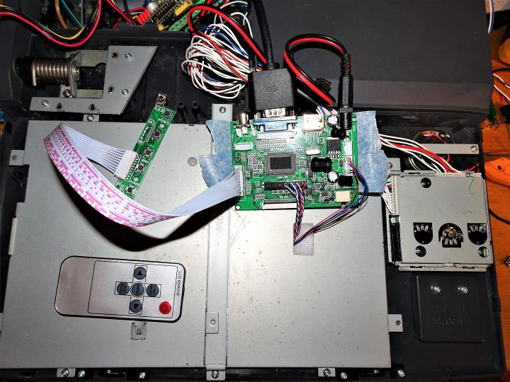
I hot-glued the LCD screen tabs to the chassis and used the original STacy shield to press it snug with foam in the middle. Very good fit. Only challenge is placing the controller as the supplied cable is quite short. I'll have to find a longer one.
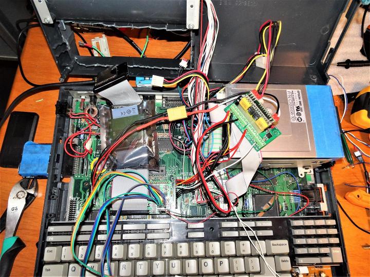
What a rat's nest :) This is a working setup. I have a MonSTer installed on top of a socket I soldered on the CPU. Best upgrade ever! CosmosEx is installed in the bottom drive bay. For the MonSTer I have the jumpers turned into cables with slider switches at the end to make changes in the battery compartment.
I changed the STacy DC-plug polarity so the center is positive, which is most common these days. I did that by switching the red and black wires coming from the left DC-DC converter plug on the motherboard. That's where the back DC-plug comes to. The wires go to the PicoPSU input jack. The original switch is used as well.

Here's the PicoPSU with the fantastic ATX-adapter from Stedy. The controller is powered from here and turns the screen on as you power the STacy. Really nice.

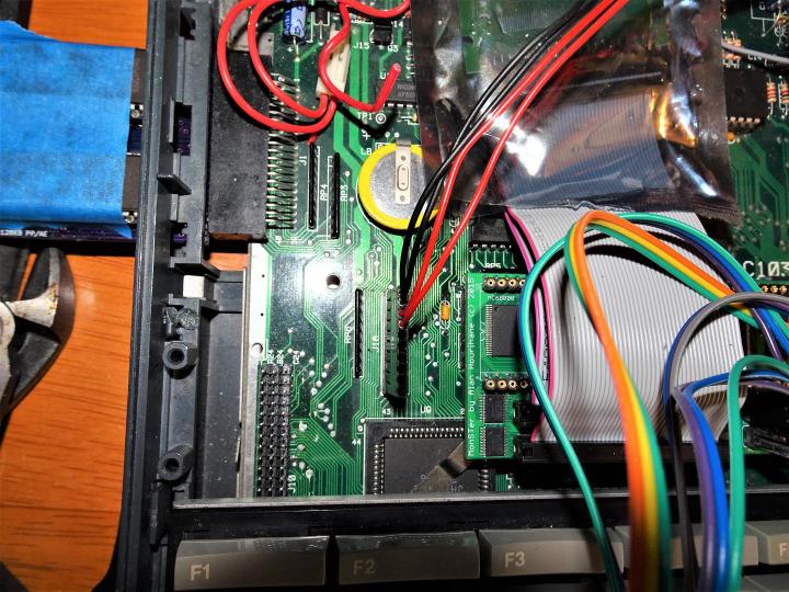
A shot of the ACSI converter. This is where you connect the MonSTer HDINT signal and to use the STacy's drive activity LED on the screen, just plug one wire from either IDE to the HDBUSY pin.
So that's it for now. Still to do:
Source longer LCD cable to better install the LCD controller.
Mask the LCD bezels
Find a better controller that scales better
Install a LaceScan maybe
Connect VGA internally
Clean up cabling.